
✍️ 前言 / Author's Note
欢迎来到我的技术博客。本文展示了一份基于全英文撰写的 FSRU(浮式储存气化装置)船用天然气压缩机改造项目的深冷管道有限元应力分析(FEA)报告。
作为一名机械设计工程师,本报告展示了如何运用 ANSYS Workbench 等工业分析软件,严格遵循 ASME B31.3 和 DNV 国际海事规范,对在极低温(-165°C)及船舶 6-DOF 极端摇晃工况下的管路系统进行结构完整性与疲劳评估。这份计算书不仅复盘了深冷管路系统设计的核心验证逻辑,也记录了在涉外工程项目中,从遵循国际规范进行力学分析,到最终交付全英文技术文档的完整闭环。
Welcome to my technical blog. This post presents a comprehensive finite element stress analysis report for the cryogenic liquid piping segment of an FSRU Gas Compressor Retrofit Project. Utilising ANSYS and strictly adhering to ASME B31.3 and DNV standards, this report evaluates the structural integrity of the piping system under extreme combined loads, including -165°C cryogenic conditions and 6-DOF marine dynamic motions. This document not only reviews the core verification logic of cryogenic piping design but also outlines the complete workflow in international projects—from conducting structural analysis based on global standards to delivering technical documentation in professional English.
⚠️ 脱敏及免责声明 (Confidentiality & Desensitization Notice):
为恪守工程师职业操守并保护企业商业机密,本报告中涉及的部分关键几何尺寸、绝对载荷数值、具体设备型号及项目涉密编号均已进行等效脱敏与重构处理。本文仅作个人工程技术能力展示与行业技术交流之用,不代表任何实际工程的最终交付数据。
1. Purpose of Calculation
For the FSRU Gas Compressor Retrofit Project, a preliminary finite element stress analysis is conducted on a highly representative core cryogenic liquid piping segment within the system.
Strictly complying with DNV maritime codes, this analysis takes a typical piping segment (Line No.: LNG-Pipe-Demo-01, refer to Appendix Figure 1) as an example to verify the structural integrity and safety of the pipeline under combined extreme loads. These loads include internal high operating pressure, extreme cryogenic temperature gradients (-165°C), 6-DOF dynamic ship motion accelerations in severe sea states, and hull deflection deformations of the FSRU vessel. Furthermore, it aims to provide accurate ultimate support reaction data for the structural design of the deck pipe supports.
2. Abbreviations and Acronyms
| Abbreviation | Description |
|---|---|
| Acc | Acceleration loads |
| ASME | American Society of Mechanical Engineers |
| ASTM | American Society for Testing and Materials |
| DNV | Det Norske Veritas |
| DN | Nominal Diameter |
| DOF | Degrees of Freedom |
| E | Modulus of Elasticity |
| EJMA | Expansion Joint Manufacturers Association |
| FSRU | Floating Storage Regasification Unit |
| G | Gravity / Dead Weight loads |
| LC | Load Case |
| LNG | Liquefied Natural Gas |
| P | Design Pressure |
| SAM | Support Anchor Movement |
| T1 | Minimum Design Temperature / Thermal load |
| T2 | Maximum or Transient Design Temperature |
| TBC | To Be Confirmed |
| TBD | To Be Determined |
| UX, UY, UZ | Translational displacements along X, Y, Z axes |
| RX, RY, RZ | Rotational displacements about X, Y, Z axes |
3. Codes and Standards
The finite element modeling, load application, and stress evaluation in this report are strictly executed in accordance with the following codes and project-specified documents:
- ASME B31.3 (2024) - Process Piping
- DNV-RU-SHIP (2025) / DNV-OS-D101 (2025)
- H2189-PYT-BAS-005_01 - General Piping Specification
- H2189-PYT-BAS-006_01 - Pipe Thickness Calculation
4. Calculation Conditions
4.1 Structural Dimensions and Layout
The specific structural configuration of the piping for this FSRU gas compressor retrofit project is detailed in the design drawing specifications. The process piping material is ASTM A312 TP316 / 316L. The pipeline adopts a design with a cryogenic insulation layer. The piping model is constructed based on the design drawings, and envelope calculations are performed for evaluation.
4.2 Design Environment and Operating Loads
The core computational load data extracted from the project specification are shown in Table 4-1 below:
Table 4-1 FSRU Piping System Design Load Data
| Load Category | Design Parameter | Value and Description |
|---|---|---|
| Sustained Loads | Design Pressure (P) | 1.0 MPa (per specification) |
| Piping Dead Weight (G) | Includes the weight of 316L steel pipes, insulation layer, and eccentric loads from heavy valve assemblies. | |
| Fluid Weight (Fluid) | Based on internal fluid density, enveloping the gravity load case of a fully filled LNG pipe. | |
| Thermal Loads | Minimum Design Temperature | -165°C (Inducing extreme contraction of the entire pipeline) |
| Maximum Design Temperature | +70°C (Enveloping maximum ambient and operating temperatures) | |
| Installation / Reference Temperature | 22°C | |
| Ship Motion and Environmental Loads | Ship Motion Acceleration (Acc) | X-dir: [±0.3g]; Y-dir: [±0.3g]; Z-dir: [±0.3g] [TBC, to be updated in the next revision upon receipt of detailed ship motion data from the Client] |
| Hull Deflection / Support Anchor Movement (SAM) | ±15 mm [TBC, to be updated in the next revision upon receipt of detailed ship motion data from the Client] |
4.3 Piping Material and Property Parameters
The property parameters of the main piping material ASTM A312 TP316L under the extreme design temperature (-165°C) and the target evaluation codes are shown in Table 4-2.
Table 4-2 Piping Material Property Parameters
| Physical Property Parameter | Value |
|---|---|
| Modulus of Elasticity E (MPa) | 1.95×10⁵ |
| Poisson's Ratio μ | 0.3 |
| Coefficient of Thermal Expansion α (mm/mm·°C) | 15.0×10⁻⁶ |
| Basic Allowable Stress [σ] | 115 MPa |
5. Finite Element Calculation Model and Load Case Setup
5.1 Model Generation and Element Selection
The advanced finite element calculation platform developed by ANSYS, Inc. (USA) is adopted as the calculation software.
- Piping Body: Simulated using the PIPE288 3D pipe element, accurately defining the inner/outer diameters and insulation layer thickness, with the LNG fluid density applied in the cross-sectional properties.
- Elbow Distortion: For prefabricated elbows (1.5D) with a nominal diameter larger than DN40, "Pipe Idealization" is enabled. The underlying element utilizes the ELBOW290 advanced elbow element to accurately capture the cross-sectional ovalization/flattening effect under complex marine torsional loads.
- Valve/Instrument Simulation: Point Mass is utilized to accurately apply the valve weight, restoring the actual eccentric bending moments exerted on the pipeline.
- Description of Pipe Support Boundary Conditions and Constraints Simulation: To realistically reflect the constraint effects of on-site pipe supports on the pipeline, this analysis abstracts the physical supports into mathematical boundary conditions in ANSYS according to the actual process layout drawings. The specific correspondences are shown in Table 5-1.
Table 5-1 Correspondence between Typical Piping Support Types and FEA Boundary Conditions
| On-site Support /Connection Type | ANSYS Boundary Condition Setup | Degree of Freedom (DOF) Constraint Description | Actual Application Location in this Model |
|---|---|---|---|
| Equipment Flange Interface / Anchor | Fixed Support | Locks all six degrees of freedom (UX, UY, UZ, RX, RY, RZ = 0) | Liquid Inlet / Liquid Outlet |
| Sliding Support | Displacement | Only restricts downward Y-direction displacement; releases X and Z translational DOFs to absorb thermal expansion and contraction | None (Currently assuming all are guides) |
| Guide Support | Displacement | Restricts Y-direction and lateral displacement; only allows sliding along the axial direction of the pipeline | All piping supports (Tentatively all are guide supports) |
5.2 Comprehensive Calculation Load Case Setup
To satisfy DNV's comprehensive review requirements for both normal process conditions and extreme sea states, this analysis establishes the following 6 core computational load cases using a step-by-step load superposition approach (detailed in Table 5-2).
Table 5-2 FSRU Piping Static and Dynamic Analysis Load Case Combinations
| Load Case No. | Assessment Scenario Description | Load Combination | Evaluation Objective |
|---|---|---|---|
| LC1 | Baseline Sustained Case (Ambient Temp, Full Load) | P + G | ASME primary stress evaluation to prevent gravity collapse due to excessive support spans. |
| LC2 | Extreme Steady-State Operating Case | P + G + T1 | ASME secondary stress evaluation to verify the overall natural compensation flexibility and prevent fracture from cryogenic contraction. |
| LC3 | Transient Thermal Shock Case | P + G + T2 | Evaluates local stress concentrations and thermal bowing caused by uneven cooling during the initial cool-down phase. |
| LC4 | Marine Dynamic Motion Case | LC2 + Acc | [Marine Core] Evaluates the safety of the pipeline under 6-DOF inertial forces from the FSRU while in a fully contracted state. |
| LC5 | Hull Deflection Bending Case | LC2 + SAM | [Marine Core] Evaluates the pipeline's absorption capacity when the deck deforms (supports being forcedly stretched/compressed) due to extreme wave loads. |
| LC6 | Ultimate Extreme Envelope Case | LC2 + Acc + SAM | [Structural Interface] The most severe combination; not used as a stress evaluation baseline, but dedicated solely to extracting ultimate support reaction loads. |
Load Component Definitions:
- G (Gravity): Includes empty pipe dead weight, insulation weight, eccentric load of flange/valve assemblies, and the weight of the full LNG fluid medium, applied vertically downward.
- T1 (Thermal Contraction): Simulates the massive overall cryogenic contraction effect when the entire pipe wall temperature drops to the extreme cold limit after entering the stable operating phase.
- T2 (Transient Thermal): Simulates the cross-sectional and axial temperature gradients caused by localized liquefaction inside the pipe during the initial cool-down phase (e.g., inlet at -165°C, outlet at ambient temperature).
- Acc (Marine Dynamic Load): The immense dynamic inertial force induced by the total mass of the system when the FSRU experiences 6-DOF motions (such as rolling and pitching) in rough seas.
- SAM (Hull Deflection Load): The forced pulling and compressing displacements exerted on the connected piping due to the relative movement of deck supports when the FSRU undergoes global hogging or sagging bending in waves.
6. Stress Analysis and Evaluation
6.1 Evaluation Criteria and Allowable Stress Calculation (ASME B31.3)
To scientifically and accurately assess the structural safety of this pipeline under complex marine conditions, this analysis strictly complies with the ASME B31.3 code. Primary stress (to prevent plastic rupture) and secondary stress (to prevent fatigue failure) are decoupled, and their respective acceptance criteria are established.
6.1.1. Primary Stress Evaluation Criteria:
The sum of longitudinal stresses caused by sustained loads such as pressure (P) and gravity (G) shall not exceed the allowable stress of the material at the design temperature.
The basic allowable stress for 316L in this project is set to: [σ] = 115 MPa.
Extracted from the pure sustained load case (LC1), the extreme primary stress of this pipeline is 55.7 MPa (≤ 115 MPa), which satisfies the code requirements.
6.1.2. Secondary Stress Evaluation Criteria:
Stresses generated by displacement constraints, such as cryogenic thermal contraction and support anchor movement (SAM), belong to secondary stress, which features self-limiting characteristics. According to the ASME B31.3 allowable displacement stress range formula, considering the significant primary stress margin of this pipeline, the unutilized primary stress capacity is permitted to be utilized for compensation (Liberal Stress Allowance):
- (Allowable stress at cold condition) = 115 MPa
- (Allowable stress at hot condition) = 115 MPa
- (Maximum primary stress) = 55.7 MPa
- f (Stress range factor) = 1.0 (The expected number of cold/hot equivalent cycles during the FSRU process piping's lifecycle is less than 7,000)
Evaluation Conclusion: For the complex marine combined load cases incorporating thermal contraction and marine dynamic deformations (LC2, LC3, LC4, LC5, LC6), the acceptance criteria for the maximum combined stress is justifiably elevated to 231.8 MPa.
6.1.3. Bellows Expansion Joint Evaluation Criteria (EJMA Standard):
The stress evaluation formulas of ASME B31.3 are not applicable to the bellows expansion joint components used to absorb cryogenic contraction in the pipeline. This analysis adopts the Equivalent Stiffness Matrix method (Bushing Joint) to simulate the mechanical characteristics of the bellows.
The evaluation criterion is: Extract the relative displacement deformations (axial, lateral, angular) at both ends of the bellows under extreme marine load cases, and this value must not exceed the maximum allowable displacement limits provided by the bellows vendor based on the EJMA standard.
6.2 Stress Calculation Results Summary Table
Computed by the ANSYS solver, the maximum nodal stress extractions and the latest baseline evaluations for each load case are summarized below:
Table 6-1 Maximum Combined Stress and Evaluation Results of Piping under Various Load Cases
| Load Case No. | Load Characteristics | Max. Combined Stress (MPa) | Allowable Limit (MPa) | Evaluation Result | Data Source |
|---|---|---|---|---|---|
| LC1 | P + G | 55.7 | 115 | Passed | See Appendix Fig. 2 |
| LC2 | P + G + T1 | 113.4 | 231.8 | Passed | See Appendix Fig. 3 |
| LC3 | P + G + T2 | 65.826 | 231.8 | Passed | See Appendix Fig. 4 |
| LC4 | LC2 + Acc | 118.47 | 231.8 | Passed | See Appendix Fig. 5 |
| LC5 | LC2 + SAM | 133.95 | 231.8 | Passed | See Appendix Fig. 6 |
| LC6 | LC2 + ACC + SAM | 141.41 | 231.8 | Passed | See Appendix Fig. 7 |
6.3 Displacement Evaluation of Bellows Expansion Joints
For the cryogenic bellows in the system, a finite element equivalent substitution has been performed based on the stiffness parameters (axial and lateral stiffness matrices) provided by the vendor. Under the extreme envelope load case, the relative deformations extracted at both ends of the bellows are as follows:
Table 6-2 Relative Displacements and Evaluation of Bellows under Extreme Load Case
| Bellows Tag No. | Extracted Load Case | Axial Disp. (mm) |
Lateral Disp. (mm) |
Angular Deflection (deg) |
Vendor Allowable Limit | Evaluation Result |
|---|---|---|---|---|---|---|
| TBD | TBD | TBD | TBD | TBD | TBD | TBD |
| TBD | TBD | TBD | TBD | TBD | TBD | TBD |
6.4 Displacement Analysis of Key Piping Nodes
To ensure that the movement trajectory of the pipeline under extreme sea states and cryogenic conditions does not clash with other hull structures, and that the displacement travel of various sliding supports remains within the safe range of the base plates (to prevent slip-off), the directional displacements of key nodes under the most severe load case are extracted as follows:
Table 6-3 Summary of Extreme Displacements at Key Piping Nodes
| Node No. / Location | Assessed Load Case | X-Disp. (mm) |
Y-Disp. (mm) |
Z-Disp. (mm) |
Remarks / Evaluation |
|---|---|---|---|---|---|
| Max. Deformation Location (Elbow) (Refer to Figure 8) | LC6 | 5.77 | -57.82 | -3.02 | Sufficient spatial envelope; no risk of structural clash. |
| Support C79 | LC6 | -10.37 | 0 | 0 | Displacement is within the safe sliding travel of the support base plate; no risk of slip-off. |
| Support C80 | LC6 | -1.92 | 0 | 0 | Same as above. |
| Support C81 | LC6 | 0 | -55.24 | 0 | Same as above. |
| Support C82 | LC6 | 0 | -46.00 | 0 | Same as above. |
| Support C83 | LC6 | 0 | -38.84 | 0 | Same as above. |
| Support C84 | LC6 | 0 | -27.22 | 0 | Same as above. |
| Support C85 | LC6 | 0 | -16.74 | 0 | Same as above. |
| Support C86 | LC6 | 0 | 2.79 | 0 | Same as above. |
| Support C87 | LC6 | 2.85 | 0 | 0 | Same as above. |
7. Ultimate Support Reaction Load Extraction
In accordance with DNV code requirements stipulating that "pipe support foundations must be capable of withstanding dynamic load impacts," the ultimate reaction loads transmitted from the pipeline to various support points are extracted under the most severe LC6 (Ultimate Extreme Envelope Case).
The following data is formally submitted as critical interface information to the overall structural discipline for the final strength verification and welding design of the deck support frames and hull base structures.
Table 7-1 Summary of Maximum Piping Support Reaction Loads under Ultimate Envelope Case (LC6)
| Support Name / Location | Constraint Type | Fx (N) | Fy (N) | Fz (N) | Mx (N·m) | My (N·m) | Mz (N·m) |
|---|---|---|---|---|---|---|---|
| TPX-06 Fixed Support | Anchor | 605.81 | 212.75 | 356.18 | 157.21 | 547.79 | 16.45 |
| TPX-07 Fixed Support | Anchor | -37.05 | 68.30 | 257.22 | 67.75 | 91.76 | -30.18 |
| DRAIN POT | Anchor | 26.41 | 1166.9 | 52.23 | 0 | 0 | 0 |
| Support C79 | Guide | 0 | 462.11 | 1592.1 | 0 | 0 | 0 |
| Support C80 | Guide | 0 | 1196.1 | 106.3 | 0 | 0 | 0 |
| Support C81 | Guide | 1634.9 | 0 | 216.71 | 0 | 0 | 0 |
| Support C82 | Guide | 143.13 | 0 | 70.02 | 0 | 0 | 0 |
| Support C83 | Guide | 126.56 | 0 | 175.02 | 0 | 0 | 0 |
| Support C84 | Guide | 74.00 | 0 | 192.45 | 0 | 0 | 0 |
| Support C85 | Guide | 75.36 | 0 | 161.23 | 0 | 0 | 0 |
| Support C86 | Guide | 275.27 | 0 | 609.44 | 0 | 0 | 0 |
| Support C87 | Guide | 0 | 1244.2 | 2107.8 | 0 | 0 | 0 |
8. Conclusion
Multi-case calculations verify that the FSRU gas compressor retrofit process piping system, under the combined effects of extreme internal pressure and heavy eccentric loads from flange/valve assemblies, exhibits primary sustained stresses far below 115 MPa. This fully satisfies the basic ASME requirements for tensile and rupture prevention.
Upon superimposing the DNV-mandated extreme full-pipe cryogenic contraction, ultimate ship motion accelerations (Acc), and forced hull bending displacements (SAM), the maximum ultimate dynamic and thermal stresses generated by the piping system are strictly controlled within the safe envelope of the 231.8 MPa secondary allowable stress, as calculated per the ASME B31.3 code.
In conclusion: The routing layout and the guide/sliding constraint design of the support system for this pipeline are highly rational. Under various extreme sea states and severe process operations of the FSRU, the system demonstrates excellent anti-fatigue flexibility as well as robust anti-motion rigidity. The structural integrity completely meets the standard requirements, proving to be safe and reliable.
The relevant ultimate support reaction loads have been fully detailed in Section VI, providing sufficient and conservative interface data for the subsequent detailed structural engineering of the deck pipe supports.
9. Appendix Documents
Appendix A: Stress Calculation Result Contour Plots for FSRU Retrofit Liquid Piping
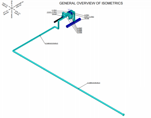
Figure 1: Isometric View of FEA Model for Piping (Line No. CL4009-SS150-50-23)
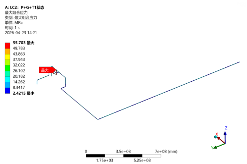
Figure 2: Stress Contour Plot of Piping under LC1
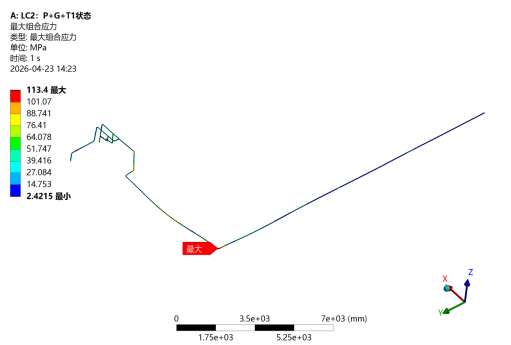
Figure 3: Stress Contour Plot of Piping under LC2
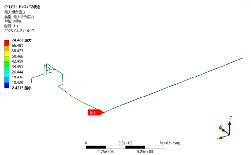
Figure 4: Stress Contour Plot of Piping under LC3
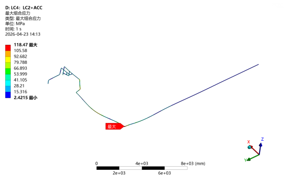
Figure 5: Stress Contour Plot of Piping under LC4
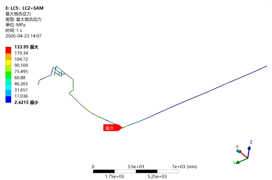
Figure 6: Stress Contour Plot of Piping under LC5
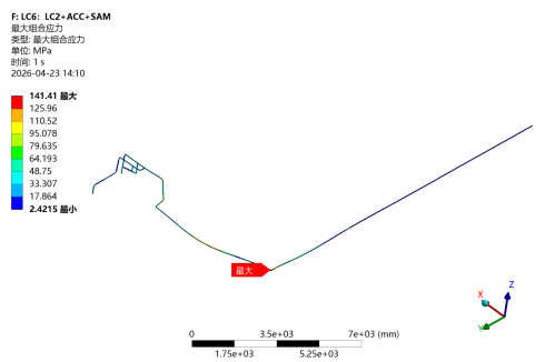
Figure 7: Stress Contour Plot of Piping under LC6
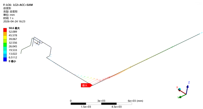
Figure 8: Total Displacement Vector Plot of Piping under LC6